Advanced Robotics Programming
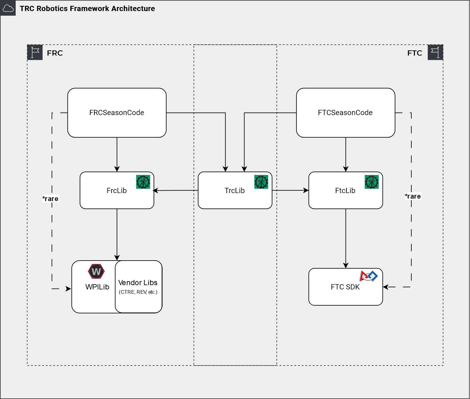
This section focuses on our Titan Robotics Framework (TRC Library). The target audience is for students who already know the Java language. The Titan Robotics Framework is designed for both FTC and FRC. After finishing this section, you should be able to write code for both FTC and FRC robots with minimal platform specific changes using our Framework Library.
Titan Robotics Framework Architecture
Framework Library JavaDoc
Programming Software Installation
Before you can start coding, you need to install the required software on your computer. Please take some time to do this at home. Software installation could be time consuming and requires downloading gigabytes of data from the Internet. Follow the instructions below for the software you need.
Code Development Process
Before diving into code development, you need to learn about ‘‘Code Development Process’’.
TeleOp Driving Your Robot Right Out-Of-The-Box
At this point, you should have installed all necessary software for developing robot code and also clone the robot template code from the GitHub repo. Since the template already contains basic code for three different kinds of robot base (Differential Drive, Mecanum Drive and Swerve Drive), it takes very few modifications to make it work with any of the three types of robots.
Basic Subsystems Provided by Titan Robotics Framework
Once the drive base is fully operational, the next step is to create subsystems for the robot. Titan Robotics Framework provides supports for many basic simple subsystems as well as more complex subsystems.
Simple Subsystems
Complex Subsystems
- Motor Actuator: Motor is the most fundamental output device on a robot. It provides movements for mechanisms. Motor Actuators contain one or more motors, an encoder to keep track of its position and some limit switches to limit their movement. FIRST provided some basic motor classes (e.g. DcMotor/DcMotorEx for FTC and Phoenix5/Phoenix6/SparkMax for FRC). The Framework Library added a lot more features on top of that in the TrcMotor class. For example, it added support for a digital input sensor to reset the motor encoder automatically (limit switches). This is useful for using the motor in a complex actuator such as an arm or elevator when you may need to zero calibrate the zero position of the actuator using a lower limit switch. It also added support to provide velocity control and motor odometry. On top of the fundamental motor features, it also provided PID Controlled functionality. It can support either native motor close-loop control (position and velocity PID control) or software PID control in case some motors do not support native close-loop control (e.g. continuous servos). TrcMotor added support for lower and upper limit switches, motor stall protection for safety, multiple motors with synchronization (motor followers), zero position calibration, gravity compensation and much more. These advanced features made it trivial to implement complex subsystems such as swing arm, elevator, slide or pan and tilt. The built-in PIDF controller allows the arm or elevator to be controlled by an analog joystick to speed up or slow down the arm/elevator movement. It understands the arm/elevator position approaching the lower/upper position limits and will automatically slow down its movement. It also provides stall protection. If the PID Actuator got stuck and the motor is stalled, it can cut motor power to prevent it from burning out. It also allows a reset timeout so that the stall condition can be cleared after a certain period assuming the stall condition is caused by human temporarily. This allows the subsystem to resume its function and provides time for the motor to cool down. In addition, it also supports voltage compensation. It understands battery voltage drop and can compensate the power level sent to the motor.
- Servo Actuator: With the limited number of motors allowed by FTC, servos become the secondary most important actuator on a robot. The Framework Library provides extended support of servo in the TrcServo class over FIRST provided SDK. It supports translation between logical servo positions (between the value of 0.0 and 1.0) to physical positions such as 0.0 to 180.0 degrees. Just like motors, it also allows you to invert the direction of the servo movement. In addition, it provides features to support multiple servos (followers) driving the same mechanism. Most importantly, it allows speed controlling a servo so you can control it by an analog joystick or simply slow down its movement.
- Pneumatic Actuator: Pnuematic Actuators are only legal for FRC but not FTC.
- Intake:
- Conveyor:
- Grabber:
- Shooter:
- Vision:
such as Elevator, Arm, Intake, Grabber etc. Even though the game of each season changes, a lot of subsystems repeat themselves season after season. Therefore, the Framework Library provides generalized basic subsystems to handle most of the scenarios. Here are some typical subsystems provided by the Framework Library.
Creating Complex Subsystems
The above section talked about how to create simple subsystems using Basic Subsystems provided by the Framework Library. In this section, we will talk about creating complex subsystems that consist of multiple Basic subsystems and will support complex operations.
It is a good practice to create subsystems as separate Java classes that encapsulate all hardware related to those subsystems. To create a subsystem, you need to answer the following questions:
- What hardware does the subsystem contain? This includes motors, sensors and a combination of other basic subsystems. For example, a complex subsystem that may consist of a wrist attached to the end of an arm that attched to the end of an elevator. This could be written as three independent subsystems. However, since the relationship of the three subsystems is such that they have dependencies on each other, and therefore, must be operated as a single subsystem. In this example, when the elevator is retracted to the lowest height, the arm is not freely movable because it will hit other components on the robot base frame. When the arm is retracted to its resting position, the wrist must be at a certain angle to fit into the resting place. Because of these mechanical restrictions, we will create a complex subsystem that encapsulates all three basic subsystems: an elevator, an arm and a wrist.
- What operations does the subsystem support? For example, the complex subsystem described above may provide a retract method that will retract everything to its resting position. This will involve a sequence of movements that will understand the positions of all three basic subsystems and will operate them such that it will not hit any obstacles in the process of retracting. It may also provide an operation to extend the mechanism to the “scoring position”. Again, it needs to sequence the movements to pull the wrist out of the resting place before swinging the arm up, for example.
Since complex subsystems are very specific on their restrictions and what they can do, we are …
Tuning Subsystems
Scale and Offset
Gravity Compensation
PID
Tuning Drive Base
Odometry
PID
Operating Subsystems In TeleOp Mode
Creating Auto-Assist Tasks
Creating Autonomous Code
Miscellaneous
Analog Control Response
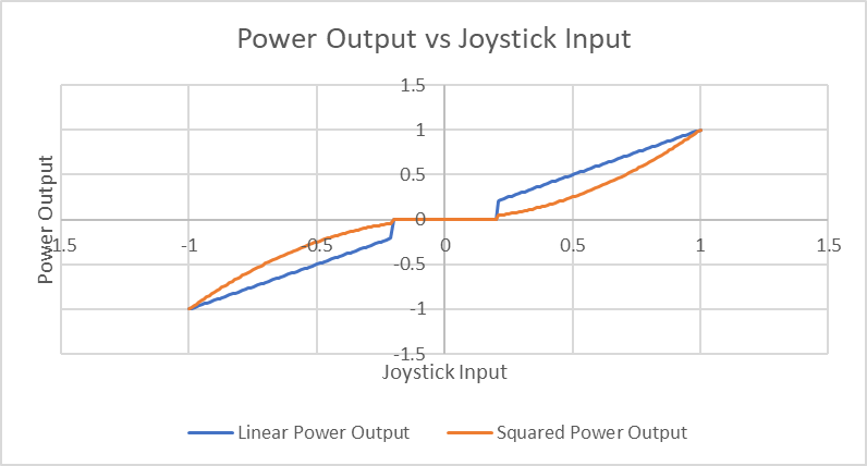
Gamepad provides a number of analog controls (e.g. joysticks and triggers). These controls give you a continuous value between -1.0 to 1.0 (or between 0.0 to 1.0) depending on how hard you pushed the control. These controls will return to their neutral positions when you let go. However, some of them such as joysticks, may not quite return to zero position. They may leave a small residual value (e.g. 0.1). As a result, if the joystick is controlling the robot drive train, you may notice the robot is still slowly creeping forward when you let go the joystick. To deal with this, we typically define a dead band within which we will return a zero value. For example, if we define a dead band of 0.2 and the joystick reads a value of 0.12 at its neutral position, we will return a zero value instead.
Typically, to move a mechanism with an analog control, one would read the value and directly apply it as the motor power of the mechanism linearly. However, there are times when you want to have more precise control of the mechanism when it is in the slow range of motion. Therefore, instead of applying the value linearly, it may be beneficial to apply it with an exponential decay curve such as a squared response curve. This gives you a wider low range and will accelerate in the narrower high range. The following diagram shows the joystick input to output response curve incorporating dead band and square response.
Increase the number of available buttons on your Gamepad
Gamepad buttons are scarce resources, but there is a trick to give us more buttons. This is basically similar to a computer keyboard or calculator keypad where you have the Alt button (or 2nd Func button). By pressing and holding the Alt button down, other buttons on the keyboard can have other functions.
Different ways of using Gamepad buttons
- Use one button to turn on and another to turn off
- Use a single button to toggle ON and OFF
- Button press to turn ON and release to turn off